Earthing or Grounding measurement resistance have a several technique and method applicable with suitable situation and location for earthing chamber.
This time i want share about 62% method of earthing measurement that popular used by all electrician around the world to get earthing resistance for Substation,lightning arrestor,generator and others electrical equipment.
The 62% method has been adopted after graphical consideration and after actual test. It is the most accurate method but is limited by the fact that the ground tested is a single unit.
This method applies only when all there electrodes are in a straight line and the ground is a single electrode, pipe, or plate, etc.
How To perform 62% method for earthing measurement?
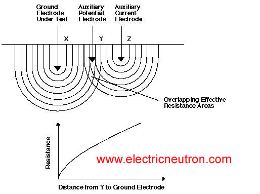
Which shows the effective resistance areas (concentric shells) of the ground electrode X and of the auxiliary current electrode Z.The resistance areas overlap.
If readings were taken by moving the auxiliary potential electrode Y towards either X or Z, the reading differentials would be great and one could not obtain a reading within a reasonable band of tolerance.
The sensitive areas overlap and act constantly to increase resistance as Y is moved away from X
The X and Z electrodes are sufficiently spaced so that the areas of effective resistance do not overlap.
If we plot the r esistance measured we find that the measurements level off when Y is placed at 62% of the distance from X to Z, and that the readings on either side of the initial Y setting are most likely to be within the established tolerance band.
This tolerance band is defined by the user and expressed as a percent of the initial reading: ± 2%, ± 5%, ± 10%, etc.
Auxiliary Electrode Spacing
No definite distance between X and Z can be given, since this distance is relative to the diameter of the electrode tested, its length, the homogeneity of the soil tested, and particularly.
The effective resistance areas. However, an approximate distance may be determined from the following chart which is given for a homogeneous soil and an electrode of 1” in diameter. (For a diameter of 1/2”, reduce the distance by 10%; for a diameter of 2” increase the distance by 10%.)


Love the detail and information provided very helpful :)