Understanding the 62% Method for Earthing Measurement
Introduction
Earthing or grounding resistance measurement is a crucial task in ensuring the safety and reliability of electrical systems. Various techniques are used to measure earthing resistance, and one of the most widely adopted and accurate methods is the 62% method. This method is especially popular among electricians worldwide for measuring the resistance of grounding systems in substations, lightning arrestors, generators, and other electrical equipment.
Why the 62% Method?
The 62% method has gained recognition due to its graphical considerations and practical testing accuracy. It is best suited for single ground electrodes, such as rods, pipes, or plates. However, it requires that all three electrodes (ground, current, and potential electrodes) are aligned in a straight line.

How to Perform the 62% Method?
- Set Up the Electrodes:
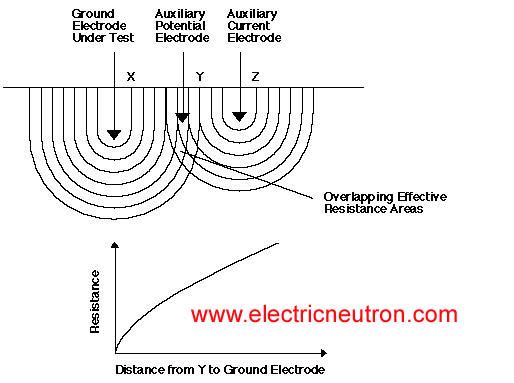
- Place the ground electrode under test (X), the auxiliary current electrode (Z), and the auxiliary potential electrode (Y) in a straight line.
- Ensure sufficient spacing between electrodes to minimize resistance overlap.
- Understand Effective Resistance Areas:
- The ground electrode (X) and the auxiliary current electrode (Z) have overlapping effective resistance areas (concentric shells).
- When the auxiliary potential electrode (Y) is placed within these overlapping areas, the resistance readings will vary significantly.
- Position the Auxiliary Potential Electrode:
- To achieve accurate readings, place the auxiliary potential electrode (Y) at 62% of the distance between X and Z.
- At this position, the resistance readings will level off, ensuring consistent and reliable measurements.
- Plot Resistance Readings:
- Move the auxiliary potential electrode (Y) slightly on either side of the 62% position and record the readings.
- Plot the values to confirm that they fall within the tolerance band (±2%, ±5%, ±10%, etc.), ensuring accuracy.

Auxiliary Electrode Spacing
- The distance between X and Z is critical and depends on:
- The diameter and length of the ground electrode.
- Soil homogeneity and resistivity.
- The effective resistance areas.
- Guidelines for Spacing:
- For a 1” diameter electrode, refer to standard spacing charts.
- Adjust spacing for different diameters:
- 1/2” Diameter: Reduce spacing by 10%.
- 2” Diameter: Increase spacing by 10%.

Advantages of the 62% Method
- Accuracy: Provides highly reliable results when performed correctly.
- Applicability: Suitable for single ground electrodes in various scenarios, including substations and lightning protection systems.
- Graphical Validation: Resistance readings can be plotted to verify consistency and tolerance.

Conclusion
The 62% method is an essential tool for electricians and engineers involved in earthing system maintenance and testing. By ensuring proper electrode placement and following best practices, this method delivers precise resistance measurements, enhancing the safety and functionality of electrical installations. For further details on other earthing measurement techniques, stay tuned for upcoming posts exploring two-point and multiple-electrode systems!
